Aircraft W&B - Part 2 - An element of efficiency
Author: Kristjan Röx
In Part 1 of this series, the fundamental requirements and building blocks of aircraft weight & balance were introduced.
The key takeaway was that weight and balance is a key element in aviation safety.
The role of weight and balance as a matter of safety only focused on the aircraft’s weight and Center of Gravity (CG) being inside the weight and balance envelope.
This is a binary requirement, i.e., either it is inside the envelope or outside. No consideration was made to where inside the envelope the aircraft's CG was, as that was not a safety concern.
In Part 2 of the series, we’ll investigate how certain CG locations inside the envelope are better than others, and how an aircraft’s weight and balance affects operational efficiency.
Content
- A few things to keep in mind
- How does W&B affect operational efficiency?
- Certain CG locations are better than others
- Loading ergonomics
- Summary
A few things to keep in mind
-
A certain CG should always be considered for a corresponding aircraft weight. The limits on allowable CG vary with weight.
-
We are typically only concerned with longitudinal CG, i.e., the location of the CG along the fuselage between nose and tail. Lateral CG also exists, but it is generally not a concern for passenger aircraft, as the load is distributed sufficiently symmetrically across the longitudinal axis of the aircraft.
-
For cargo aircraft, lateral CG may also be evaluated and compared with associated limits.
In this article, we’ll be discussing only longitudinal CG.
How does W&B affect operational efficiency?
The weight and balance of an aircraft will affect two aspects of operational efficiency:
-
Firstly, the aircraft's CG, which is determined by the load distribution, affects the fuel efficiency of the aircraft in flight. Therefore, certain CG locations are better than others.
-
Secondly, the distribution of load on an aircraft determines the process of loading and unloading the aircraft before and after flight, respectively, which then affects the same process on the next flight of the aircraft and so on. Certain load items have higher priority than others and must be offloaded first. Overall, efficient loading and unloading processes strike a balance between the time they take and the resources they require. We’ll refer to this aspect of efficiency as loading ergonomics.
We’ll look into each of these aspects in more detail.
Certain CG locations are better than others
CG locations further aft along the aircraft fuselage are better.
Question: In what sense are aft CG locations better?
Answer: Aft CG reduces the aircraft’s aerodynamic drag, which then reduces the required thrust from the engine, which saves fuel.
To explain why this is the case, we need to apply some physics and mathematics. If that is not your forte, please follow along nonetheless, as commentary is provided along the way.
The math
Consider a transport aircraft with weight in steady and level flight at an angle of attack relative to the oncoming airflow. The figure below shows such an aircraft and the forces acting on it due to the wings and tail, as well as its own weight. For our demonstration, we only need to consider those forces.
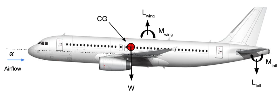 A typical transport aircraft in steady flight.
The lift and moment from the wing are applied at the same point - the aerodynamic center of the wing. Similarly, the lift and moment of the tail are calculated at the aerodynamic center of the tail.
The aerodynamic center of a lifting surface is a point of convenience. The convenience associated with this point is that the moment becomes independent of the angle of attack . Therefore, in our model, both and are constants with respect to .
The aerodynamic centers of the wing and tail are fixed points on the aircraft's geometry. therefore, we can define the distances and , which represent the distances between the aerodynamic centers of the wing and tail, respectively, and the CG.
Since the aerodynamic centers are fixed, the distance between them is also fixed. Therefore, we can also define their fixed spacing .
For a steady state to prevail, the aircraft must be in both a force and moment equilibrium according to Newton's 2nd Law. To establish this, the sum of all forces and moments, separately, must vanish (i.e., be zero).
First, let’s look at the forces:
This tells us that the total lift of the aircraft, i.e., the sum of lift from wing and tail, must be equal to the aircraft’s weight. The boxed relation will be used later on.
Next, let’s look at the moments (around the CG):
Here, we have rearranged the terms of the moment equilibrium criteria and isolated the lift of the wing .
We can now use the boxed result from the force equilibrium above and replace with the relation . This gives us
Remembering that and thus , we obtain
Here we have derived a relationship between the wing’s lift and the CG location relative to the wing through . Other parameters are constants.
We can also isolate the lift from the tail as
What is interesting to investigate is how changes if the CG is moved, i.e., if changes.
Mathematically, we do this by checking the derivative , which is
Which is positive and constant at given weight .
For a small finite change in the CG location , we can then determine the associated change in the wing’s lift as
Right…what does this tell us?
-
If we move the CG forward, then is positive as the distance between the CG and the wing’s aerodynamic center increases. This makes positive, i.e., the lift increases.
-
If we move the CG aft, then is negative, and is also negative, i.e. the lift decreases.
Therefore, a more forward CG location requires the wing to generate more lift.
More lift, more drag
We have established that a more forward CG requires more lift from the wing.
The fuel burn of an aircraft is determined by the required thrust from the engines. For steady flight, the thrust must be equal to the drag .
The total drag of an aircraft in steady flight can be modelled with its drag polar as
Where:
-
is the zero-lift drag of the aircraft.
-
and are the lift-induced drag components of the wing and tail respectively. This component from the tail is also called trim drag.
-
and are efficiency factors of the wing and tail lifting surfaces, respectively.
-
and are the lift-coefficients of the wing and tail respectively.
-
is the reference surface area of the wing.
-
is dynamic pressure.
As the wing is a much larger lifting surface than the tail, its contribution to lift-induced drag is also much larger. Therefore, the drag polar can be simplified, without loss of generality, to
This is also the reason we focused on in the previous section.
The wing lift from before, , can be written as
So, at constant dynamic pressure (i.e., fixed altitude and speed), the lift is proportional to (i.e. the angle of attack ).
We are now interested in the change in drag with lift, i.e., the derivative .
Taking the derivative of the simplified drag polar with respect to the , we obtain
where the bracketed term is always positive and for positive lift.
Therefore, a small finite increase in the wing lift through the lift coefficient yields a finite change in drag .
For an increase in lift, i.e. , then , representing an increase in drag.
For stability reasons, the CG location must be forward of the wing's aerodynamic center, i.e. .
Tying it all together
At last, we have shown that a more forward CG requires more lift from the aircraft’s wing.
We have also shown that a higher lift from the wing results in higher drag on the aircraft, as it causes higher lift-induced drag.
The higher drag will require higher thrust from the engines to maintain steady flight.
Consequently, higher thrust requires more fuel to be burned. Loading the aircraft at maximum possible aft CG would constitute a Minimum drag loading.
But - there are limits to how far aft the CG can be, both due to the aircraft design and for operational reasons. We must also consider other limitations in the load planning process, which will be discussed in a later article.
Loading ergonomics
The loading and unloading process of an aircraft must occur within the time available between flights, i.e., during the turnaround of the aircraft. This process also has to harmonize with other processes that have to occur to during the turnaround.
Many airlines operate a hub-and-spoke system - where load on one flight is connecting onto another flight. This applies to passengers, bags, and cargo.
This type of network makes the turnaround process of one flight dependent on the incoming flights in two key ways:
-
The aircraft itself has to be unloaded after landing and loaded for the next depature.
-
Connecting load from other inbound flights has to be offloaded from those flights and transferred to the next.
This other network type is point-to-point, where each flight only carries load from an origin to a destination - with no other dependencies. The only dependency is the aircraft, which has to be used on a later flight. Load is fully independent in this network.
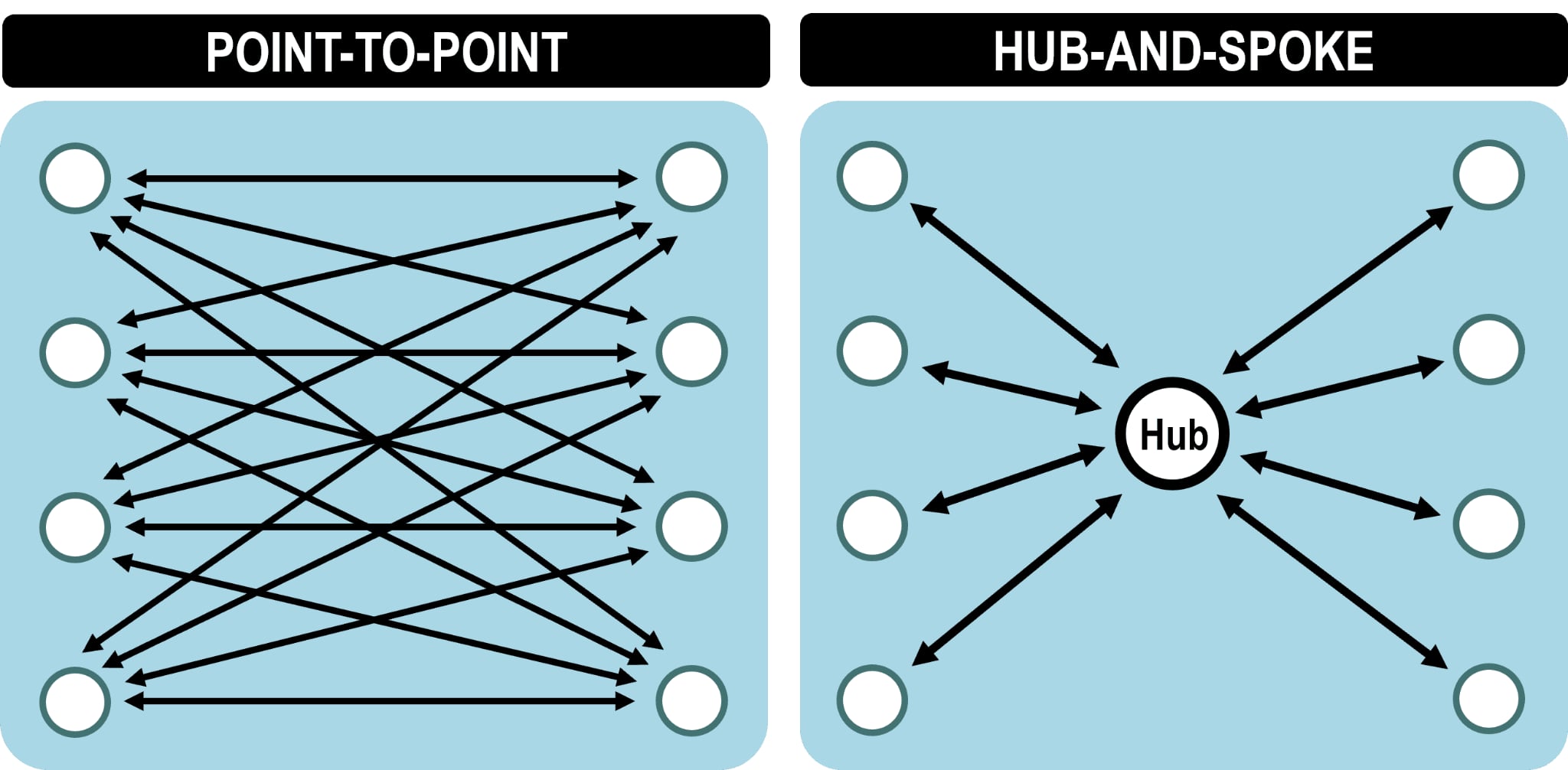 Hub-and-spoke versus point-to-point networks
The ergonomic aspect of weight and balance is very important for an efficient hub-and-spoke operation on the ground.
Load items must be arranged and distributed in the aircraft holds in such a way that it can be efficiently unloaded and then loaded again.
-
Special consideration shall be placed on connecting load - which must be offloaded first to minimize connecting times.
-
The connecting load shall be separate from other types of load - i.e. no mixing - and possibly separated furhter by final destination.
-
The load distribution does also have an effect on the total time the loading/unloading process takes - and how much resources it required (equipment, labor etc.).
One could then define a Minimum time loading - which is optimal with respect to ground operations.
Summary
Not only is aircraft weight and balance an important safety check before every flight - it is also a key element in efficient operations.
Flying with an aircraft's CG further aft reduces drag and thus fuel burn. The distribution of load in the aircraft also affects ground operational efficiency, in particular for hub-and-spoke airline networks.
These elements appear to be competing objectives - i.e. we want an aft loaded aircraft but also must distribute load to ensure efficient ground operations. Increasing fuel efficiency at the cost of more inefficient ground operations has no effect on the bottom line.
The concepts of Minimum drag loading and Minimum time loading were introduced - which are optimal with respect to fuel efficiency and ground operations respectively.
Considering these possibly competing objectives, a Minimum Cost Loading can be defined - which combines these two objectives and finds an optimal trade-off to achieve minimum overall cost.
A balance must be struck between these objectives on each flight - which must be considered as part of Airline Load Control.
✈️ Coming up next: Part 3 - How airlines do Load Control.
📩 Questions or insights? Contact Tekna by DM on LinkedIn or via email to info@tekna.is
🔗 Follow Tekna on LinkedIn for future updates.